
 By Sarah Xiao
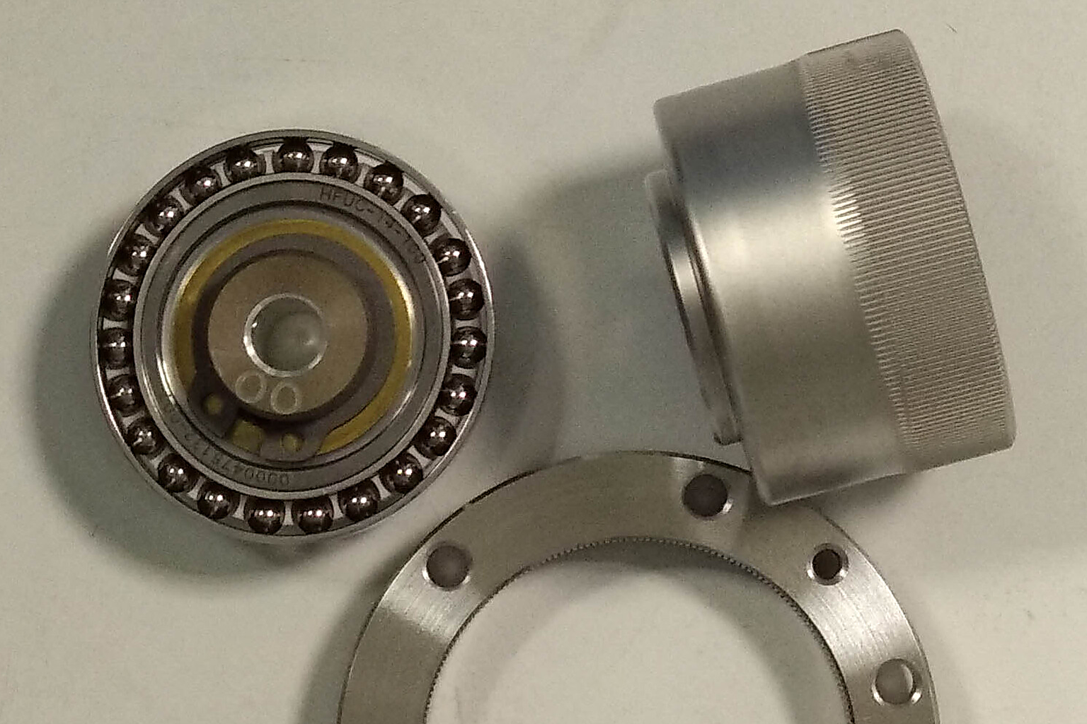
A humanoid robot carries around seventy position sensors, by most industry counts — seventy-one in one published tally. The overwhelming majority of them are magnetic encoders.
Open a joint module built in the last two years and something else is happening: the ring around the joint is being converted to inductive sensing. A 2026 encoder market analysis already files it as “the mainstream route for robot joints.”
The reason is not “better immunity to magnetic interference,” as a sentence. The real difference sits one step upstream: the two sensors do not measure the same quantity at all. We put optical, magnetic and inductive encoders on one comparison table before. This piece answers a narrower question — if you move the joint ring to inductive, what is the bill?
Start with the duty profile
A joint is not a bench. Four conditions hold at the same time, and each one is hostile to a position sensor.
Stray field. Motor, drive and power cables all sit within centimetres. Current moves, the field moves. The interference is not far away; it is attached to the thing being measured.
Heat. A joint in continuous duty runs above 100 °C internally, with sources citing the 150 °C order of magnitude.
Space and structure. Thin axially, with a hollow bore for the harness. The sensor cannot take volume, and it cannot block the routing path.
Dust, oil, vibration. Robots leave the factory floor for the field. Environmental tolerance is a pass mark, not a bonus.
Stack those four and it is obvious why optical encoders are rare inside joints: highest accuracy, worst tolerance to a dirty light path.
The measurand decides everything
This is the hinge of the whole argument.
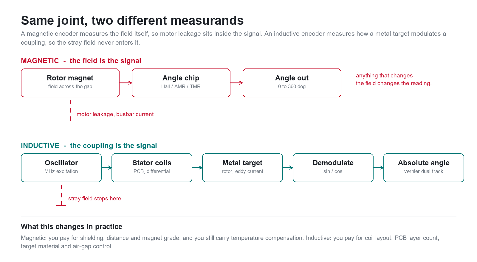
A magnetic encoder measures a magnetic field. Whether the chip senses field strength with Hall elements or direction with AMR or TMR, the signal is the state of the field at one point. The field is the signal.
An inductive encoder measures a coupling. A metal target on the rotor carries eddy currents induced by an AC excitation field, and those currents change the coupling between the excitation coil and the receive coils. Angle lives in how much the coupling is modulated — not in the outside field.
Every trade-off downstream follows. If the measurand and the disturbance are the same physical quantity, you can only compensate with shielding and distance. If the measurand does not contain the disturbance at all, there is nothing to compensate.
Three walls for magnetic encoders in a joint
Stray field enters the measurand directly. This is not noise added on top of a signal; it changes the quantity you are trying to measure. Motor leakage and the magnet ring’s own field superpose in space, and the chip cannot separate your field from the rest.
The magnet has a temperature temperament. Ring flux varies with temperature, and in extreme cases the magnet demagnetises irreversibly. An accuracy figure is quoted at a temperature. Whether it holds when hot depends on the magnet grade and the compensation.
The ring has a size. Producing a field uniform enough to read requires diameter and thickness. On a large hollow bore with a thin axial envelope, the ring often does not fit — or fits without the uniformity you need.
All three walls lead to the same place: as long as the measurand is “how strong is the field and which way does it point,” the constraints do not go away. New packaging, new shielding, a better magnet grade — each just moves the wall.
Inductive: change the measurand
The structure is a PCB stator and a conductive rotor. Excitation coils on the stator drive a high-frequency field, commonly in the MHz range. The metal target on the rotor carries eddy currents that modulate the coupling into the receive coils, which produce sin/cos signals that vary with angle; synchronous demodulation and an arctangent turn those into an angle.
What is being measured is how much the coupling is modulated, not the external field. Static external fields and motor leakage do not enter the process, so they are not disturbances. Published measurements show this class of design working under external stray fields in the thousands of A/m.
That is immunity by principle, not by shielding.

Where the accuracy comes from
Immunity explains reliability, not precision. Two design moves explain the precision.
Differential reception. Receive coils are laid out in a differential pattern, with adjacent segments wound in opposite normal direction. In the ideal case the direct coupling from excitation to receive cancels, and what remains is mostly the eddy-current modulation from the target. Common-mode errors that move both channels together — thermal drift, supply variation — cancel dynamically. Published material describes one inductive encoder chip using a three-layer PCB with double-sided sensing and a dual-rotor common-mode differential structure; layer count and topology vary by part.
Vernier dual track. One track produces a periodic signal: an electrical angle with N repeats per revolution, where N is the spatial period count. That cannot identify a mechanical angle. Add a coarse track at a different spatial frequency and compare phases, and you get a single-turn absolute angle:
θ = (φB − φA) / (f1 − f2) × 360°
The smaller the frequency difference, the larger the amplification and the finer the resolution — and the more sensitive the result is to signal quality. The chip handles unwrapping and the power-on initial value.
The bill: three line items
Heavier front end. Excitation and synchronous demodulation mean more analog engineering than a magnetic part. Integrated chips absorb most of it, but the PCB goes to four to six layers with excitation and receive coils to route. Exact layer counts depend on the part and the geometry; the era of a two-layer board with ordinary traces is over.
Sensitivity to nearby metal. Coupling is sensitive to conductors around it. Published COMSOL studies show three effects: a ground plane placed near the coils introduces a first-harmonic error that grows with distance; changing the angle between the feed lines to the receive coils from 60° to 120° measurably improves accuracy; and a two-layer, 1.6 mm gap stack-up is clearly worse than a four-layer board. These are not footnotes — they convert into degrees.
Air gap and target material. Coupling falls as the gap grows: bigger gap, smaller signal, more gain needed, worse signal-to-noise. Prefer non-ferromagnetic targets — copper, aluminium, stainless steel. Ferromagnetic targets concentrate flux and suppress eddy currents, so they are generally avoided. Target geometry also has to match the sensor’s spatial period.
Put bluntly: magnetic encoders spend their engineering budget on the magnet ring and the tolerance stack; inductive encoders spend it on the coils and the board.
Three questions before you commit
- Is there room on the stator side for a four-to-six-layer PCB carrying coils?
- Can the rotor carry a conductive metal target — copper, aluminium, stainless — instead of a permanent magnet?
- After assembly, do the air gap and eccentricity leave enough rotation for the chip’s self-calibration?
All three are “can it,” not “is it good.” A principle-level advantage does not survive a structure with no room.
Selection table by joint constraint
| Constraint | Optical | Magnetic | Inductive |
|---|---|---|---|
| Strong stray field | Unaffected | Sensitive | Immune by principle |
| High temperature | Fair | Magnet drift, demagnetisation risk | No magnet, low drift |
| Dust, oil, vibration | Sensitive | Tolerant | Tolerant |
| Hollow or thin axial envelope | Complex | Limited by ring size | Flexible PCB routing |
| Nearby metal parts | Minor | Minor | Sensitive |
| PCB demand | — | Two layers, ordinary traces | Four to six layers with coils |
The old shorthand still holds: magnetic fears crosstalk, optical fears dirt, inductive fears metal.
What this means
- The two routes differ in the measurand. Magnetic encoders measure a field; inductive encoders measure how a rotor modulates an electromagnetic coupling. Stray-field immunity is therefore a property of the principle, not of the shield.
- Inductive accuracy comes from differential reception, a vernier dual track and self-calibration. The price is a four-to-six-layer coil PCB and a heavier front end, and layout details — ground plane distance, feed-line angle, layer count — turn directly into angular error.
- Sequence the decision: duty profile first (field environment, temperature, space and mounting), then accuracy and interface, then cost and PCB burden.
The sensor in a joint is not chosen by a datasheet in the end. It is chosen by the structure around it.